Code Repo    |     RSS
MD's Technical Sharing


Tuesday, March 11, 2014

Using picojpeg library on a PIC with ILI9341 320x240 LCD module

I purchased a 320x240 LCD module which supports 320x240 resolution and comes with an SD card slot from eBay:


This LCD is using the ILI9341 controller supporting SPI mode. Within minutes I was able to sketch a program which draws text and graphics on this LCD without difficulty based on the sample code provided by adafruit:


Since the LCD resolution is high, I decided to attempt something which I have never done before, and which many hobbyists consider a great challenge on this 16-bit micrcontroller: decoding and displaying JPEG images from the SD card.

Finding a JPEG decoder library

The first candidate that came to my mind was the Microchip Graphics Library, specifically built for 16-bit and 32-bit PICs, as I have good experience with their Memory Disk Drive library, which is very robust and capable of handling various file systems. However, a quick look at the files after download revealed that things are not so simple - the library sample application is made to work with various PIC families and is designed to read graphics images from certain flash memory chips and display them onto a few supported LCD displays. As my ILI9341 is not supported, I figured that it would be a challenge to clean up the code just to get the part that I wanted, and decided to find a cleaner JPEG decoder library.

With some research, I chose picojpeg, an open source JPEG decompressor written in C in a single source file with specific features optimized for small 8/16-bit embedded devices. After getting the sample application (which converts JPEG to TGA files) working using Visual Studio, I proceeded to port the library to C30.

Porting picojpeg to C30

The library consists of just 2 files, picojpeg.c and picojpeg.h which use standard ANSI C and should compile under C30 with no issues. However, the sample application, jpg2tga.c which contains example code to use the library to decode JPEG, is written with Windows and Visual Studio in mind and will need adjustment to work under C30. Specifically, declarations with int, long and similar data types will need to be modified as int on Windows defaults to 32-bit whereas it is 16-bit in C30. Also, since right shifts under C30 are always unsigned, the following preprocessor will need to be declared and set to 1, as commented in picojpeg.c, otherwise the colors displayed will be wrong:

// Set to 1 if right shifts on signed ints are always unsigned (logical) shifts
// When 1, arithmetic right shifts will be emulated by using a logical shift
// with special case code to ensure the sign bit is replicated.
#define PJPG_RIGHT_SHIFT_IS_ALWAYS_UNSIGNED 1


By adapting the code from the jpg2tga sample application, I wrote a helper file, jpeg_helper.c, with the following function to read a JPEG file from the SD card and draw on the LCD.

JPEG_Info pjpeg_load_from_file(const char *pFilename, int reduce, unsigned char showHorizontal)

Pass 1 to showHorizontal to display the image in landscape mode on the screen. Pass 0 to display it in portrait mode.

As image data in a JPEG file is internally stored as a number of relatively small independently encoded rectangular blocks, usually 8x8 or 16x16, called Minimum Coded Units (MCU), one does not have to read the entire JPEG file into memory before displaying it. Therefore, even with the limited memory of a PIC, it is possible to display big JPEG files (subject to file system size limitation and LCD resolution) on the LCD by reading data and decoding them as the image is being rendered. This also makes it possible to load a scaled-down version of a high resolution JPEG file by simply rendering the first pixel of each MCU block, instead of the whole block. To display a scaled-down version of the image, pass 1 to the reduce parameter.

For simplicity, the jpeg_load_from_file function does not handle grayscale JPEG files.

With the above changes, I managed to use the picojpeg library to display a 320x240 JPEG on the LCD. At 32 MHz clock speed on a PIC24HJ128GP202, it took 10 seconds for the PIC to finish reading the image data from the SD card, decoding the image and display on the LCD. The process is shown in the following video.


The original photo can be downloaded here.

In my test, by plotting only the first pixel of each MCU, on the same PIC configuration, a 2816x2112 (2.41MB) JPEG file finished rendering on the 320x240 LCD in 105 seconds with no issues.

Overclocking the PIC

Although it is amazing to me that a 16-bit micro controller at 32 MHz is able to render big JPEG files, the speed (10 seconds for a 320x240 image and 105 seconds for a scaled-down display of a 2.41MB image) is too slow for any practical purposes. For a faster rendering speed, I decided to operate the PIC at a faster clock speed. Still using the internal oscillator, this is done by increasing the frequency multiplier:

// Using internal oscillator = 7.37MHz
// Running Frequency = Fosc = 7.37 * PLLDIV / 1 / 2 / 2 
// Output at RA3 = Fosc / 2 
CLKDIVbits.FRCDIV = 0;      // FRC divide by 1
CLKDIVbits.PLLPOST = 0;     // PLL divide by 2
CLKDIVbits.PLLPRE = 0;      // PLL divide by 2
PLLFBDbits.PLLDIV = 15;     // Freq. Multiplier (default is 50)

According to the datasheet, the PIC24HJ128GP202 can run at a maximum of 80MHz @ 40 MIPS, by setting the multiplier to approximately 43. During my experiment, the PIC still seems to run at 100MHz and is able to do simple UART communications, although the device would get slightly hot. Above 100MHz and up to 120MHz issues start to arise, for example, program would terminate unexpectedly with MPLAB reporting "Target Halted.". By opening View > File Registers and examining the RCON register at address 0740, it looks like a brown-out reset has occured (bit 1 of RCON is set, sometimes bit 0 is set as well). On the PIC24HJ128GP202, there is no way to turn off the brown out reset feature - it is unconfigurable. Above 120MHz, MPLAB would not even successfully start debugging the program on the PIC using PICKit2.

PIC clock speed vs. SD card SPI speed

At high clock speed and with the internal oscillator, there will also be problems of selecting the correct BRG value for the UART baud rate - in fact when testing at 100MHz, I could only get UART to run at 9600bps! As UART is mostly used for debugging in my case, this should not be an issue. Another greater issue is with the SD card SPI clock speed as many older SD cards support up to 20MHz only but the MDD library by default runs the SD card SPI clock at 1/4 of of the PIC clock speed. This is seen in the SYNC_MODE_FAST declaration in SD-SPI.h:

// Description: This macro is used to initialize a 16-bit PIC SPI module
#ifndef SYNC_MODE_FAST
    // primary precaler: 1:1 secondary prescaler: 4:1
    #define   SYNC_MODE_FAST    0x3E
#endif

This means that even at just 80MHz PIC speed, the SD card SPI speed would be at 20MHz - reaching the maximum supported speed of some cards. To work around this, the SPI pre-scalers would need to be changed to 8:1 to reduce the speed to just 10MHz:

#define   SYNC_MODE_FAST    0b111010

This reduces the SPI speed by half, making reading of SD card data and rendering of the image slower, defeating the purposes of overclocking.

In my tests, even at just 64MHz, intensive reading of JPEG data from the SD card would fail randomly and unexpectedly if the circuit is built on a breadboard. Migrating to a strip board fixes the issue and allows the clock speed to be increased. I attributed it to stray capacitance on the breadboard which becomes a problem as the SD card SPI frequency increases. In fact, 32 MHz is the maximum speed at which I could get the circuit running reliably on a breadboard.

The MPLAB source code of the ported picojpeg library can be downloaded here.
Read More »

Sunday, January 15, 2012

The good old days: cracking 16-bit DOS games

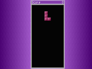
I recently wanted to play one of my favorite old games again, Zentris for DOS by Zensoft and realized how much things have changed. First, my 64-bit version of Windows 7 doesn't like 16-bit DOS apps and refuse to run the game:


Attempting to run on another computer with 32-bit Windows 7 fails because Windows Vista and above no longer supports 16-bit apps in full screen mode required by the game. Although there are various hacks to remove the restriction - some of which may prevent Windows Aero from working, the proper solution is to use DOSBox, which helps me get the game running:

However, because the version I have is a demo version, I was soon irritated by the numerous registration prompts:


Since the full version is no longer available for purchase/download either from the official website or from various abandonware sites, with some time at hand, I decided to disassemble the source code in order to remove the registration prompts.

Decompiling the code

My first attempt was to use the Interactive Disassembler to analyze ZENTRIS.EXE. However, this failed with error "sp-analysis failed" and showed an incomplete disassembly:

sp is short for stack pointer. In other words, IDA was unable to identify where the sub-functions start or end, presumably due to unexpected changes in the value of the sp pointer, and stopped analyzing the EXE file. I found this post which suggests manually identifying the sub functions. Not an easy task!

The proper solution is to be aware of the fact that the executable has been packed to save disk space, preventing IDA from disassembling it. Using my favorite DOS packer analyzer, unp411, I was soon able to detect that ZENTRIS.EXE has been compressed using PKLITE and unpack it:

IDA now disassembled the file properly:


However, now the unpacked game didn't even seem to run but instead complained "File ZENTRIS.EXE has been illegally modified". The author has implemented integrity check of the executable file to prevent exactly what I am attempting! What a hassle, but in the end I successfully used Turbo Debugger (IDA does not support debugging 16-bit apps) to locate the various checks, and use HIEW to replace these instructions with 90 NOP, allowing the unpacked game to run.

Removing the registration prompts

It's only now that the real fun began - removing the various registration prompts. Using the same technique as above, I was able to remove the text-mode prompts before and after the game, and the modified game runs flawlessly till the end, when an error message "Divide Error" is shown upon exit:

I am unable to identify where exactly this error is coming from. From Turbo Debugger disassembly it seems that the error occurs after a RET instruction - most likely due to some previous instructions overflowing some segment registers. Ignoring the error since it does not seem to affect the game functionality, I decided to proceed to try to remove the graphical registration notice.

For a moment I was not able to find any references to the main game logic in ZENTRIS.EXE. It was only then that the structure of the game is clear to me. ZENTRIS.EXE is only used as a loader that loads ZENTRIS.OVL as an overlay. ZENTRIS.OVL is then responsible for the main game logic.

ZENTRIS.OVL is also compressed, surprisingly twice. It is first packed with PKlite and then linked with the EXEPACK option:


Luckily there are no other integrity checks on ZENTRIS.OVL and the game still runs perfectly with the unpacked version of ZENTRIS.OVL.

The challenge

However, I never found a way to make Turbo Debugger step into the unpacked ZENTRIS.OVL in order to locate the call to display the graphics registration prompt. In fact, under Turbo Debugger, the main game wouldn't even start, complaining "out of memory" when trying to load the overlay. It is unclear to me why the game has to be designed this way, perhaps to limit the main executable size to less than 64K (the unpacked ZENTRIS.EXE is already 60K), or more likely, to make disassembling the game a hassle.

The only approach was to use IDA to make an educated guess on which instruction is responsible for the prompt, and then use HIEW to replace them with NOP. Inside ZENTRIS.OVL, I was able to identify a few calls to DOS INT 16h, responsible for keyboard monitoring. Replacing them with NOP and the game was indeed affected, either stopped responding at the menu, or showed the registration prompt and stopped responding without accepting keyboard input. This proved that I was on the right track.

Unfortunately, the actual counter to how long the prompt should be displayed or the correct way to remove the prompt was never found. In fact, some functions around the "suspected" area are not disassembled properly by IDA, with some instructions still showing as data bytes. It seems as if the author has obfuscated the source code to prevent disassembling. Unless I find a way to step into ZENTRIS.OVL at runtime, at this point it is not worth the time and efforts for me to proceed further.

The modified ZENTRIS.EXE with the text mode registration prompts removed, which is good enough for me :), can be downloaded here. The original game can be downloaded here. I hope someone with the right expertise can give me some hints on how to step into ZENTRIS.OVL and complete the hacking job :)


UPDATE (May 2013)
Thanks to an anonymous reader, the hacking challenge has been completed and the modified version of the game with all the registration prompts removed can be downloaded here. The complete removal of all the demo prompts (including the graphics registration screen) is done by applying a six-byte patch to the decompressed ZENTRIS.EXE and ZENTRIS.OVL files, detailed below:

File integrity check - ZENTRIS.EXE - Offset: 0x8ca8 - patch to 0xcb
First registration prompt - ZENTRIS.EXE - Offset: 0x94e2 - patch to 0xe9 0xb5
Graphics registration screen - ZENTRIS.OVL - Offset: 0x9e5f - patch to 0x0d
Closing demo prompt - ZENTRIS.EXE - Offset: 0x926a - patch to 0xeb 0x5c

Refer to the comments section of this article for several techniques that are useful in debugging old DOS games. Take note that the download link and all information provided in this article as well as the comments that followed are strictly for educational purposes only. Whenever possible, please support the author by always purchasing paid software via official means.

See also:
Programming Nostalgia: revisiting Mike Wiering's Mario game written in Pascal
Read More »

Sunday, July 24, 2011

The old new thing: mathematics of paper folding

A few weeks ago I received the following quiz as one of the questions for an exam. The question is about paper folding, something that we all know from an early age, and seems simple but it seems that no-one could answer it. I presented it in this article with my proposed solution in an attempt to show how a frustrating mathematics problem could be set from something so simple in our everyday life.

The Problem

Fold a sheet of A0 paper (841mm x 1189mm) in such a way that the longer side (1189mm) is divided into half its length, you will get a sheet of A1 paper (594mm x 841mm). Do the same for the resulting piece of paper and you'll get a sheet of A2 paper (420mm x 594mm). Repeat the same twice and you will get the commonly used paper size, A4 (210mm x 297mm). This process could repeat over and over again to get a paper size of An after n times, as demonstrated in the following diagram:

Now let us define an "inner fold" as the line created on the original paper when you fold it into half, unfold it and look at it from the front:

On the contrary, if you look at the resulting paper from the back, you will see an "outer fold".

After n steps, unfold the original piece of paper and place it in front of you. Now calculate the number of "inner" and "outer" folds created on the paper (You position the paper and look at it the same way as how you did when you started folding it for the first time).

An example for up to n=3 is demonstrated in the following diagram. A normal dashed line indicates an inner fold while a bold dashed line indicates an outer fold.
 
The number of inner and outer folds for up to n=6 is shown in the following table. Notice that if a fold is intersected by another fold, it is counted as 2 folds.

n
Inner Folds
Outer Folds
Total
0
0
0
0
1
1
0
1
2
3
1
4
3
6
4
10
4
14
10
24
5
28
24
52
6
60
52
112

The first task is to find a general formula or algorithm to calculate the number of inner and outer folds after n times.

My Proposed Solution

As simple as it seems, there is no quick solution the problem. Since most people don't have an A0 sheet of paper at home to try to fold so many times, they can only attempt with the common A4 paper and get frustrated after a short while when the paper becomes too thick to fold or the number of folds too big to count.

I proposed a simple solution below. My research also shows that there are several other approaches which may yield seemingly different formulas. Do not read it until you have attempted the question.:)

First let us simplify the problem by calculating the total number of folds first. It is simply the total number of grid segments on the original piece of paper after n steps.

We first observe the total number of horizontal (from left edge to right edge) lines and vertical (from top edge to bottom edge) lines after every fold:

n
Horizontal
Vertical
1
1
0
2
1
1
3
3
1
4
3
3
5
7
3
6
7
7

This can be generalized into:

Now look at each horizontal and vertical line and calculate the number of segments on each line:

n
Segments
/hori. line
Segments
/vert. line
1
1
0
2
2
2
3
2
4
4
4
4
5
4
8
6
8
8

This can be generalized into (for n=2 and above)
 The total number of folds after n steps is simply:

No. of horizontal lines x No. of segments on each + No. of vertical lines x No. of segments on each

With some efforts we are able to derive the formula for the total number of folds:
Now that we have found out the total number of folds, let's calculate the difference between the number of inner folds and outer folds after each step:

n
Inner Folds
Outer Folds
Diff.
1
1
0
1
2
3
1
2
3
6
4
2
4
14
10
4
5
28
24
4
6
64
56
8

Surprisingly enough, the difference is simply:
I leave this as an exercise for the reader to prove why. With the sum and the difference known, we can now calculate the number of inner and outer folds easily:
The first part of the problem is now solved. You can compare the results from our formulas with the example to make sure that the formulas are correct. Interestingly, the total number of folds after each step is equal to the number of outer folds in the next step.

Bonus Question

This is the next part of the problem: 

"So far you have always been folding by the longer side of the resulting paper after every step (so that you could get an A1 paper from A0, A2 from A1, A3 from A2 and so on). Now you are told that this restriction is no longer necessary and you could fold the paper by either the shorter or the longer side. For example, fold an A0 paper (841mm x 1189mm) by the shorter side and you will get a piece of paper of size 420mm x 1189 mm. 

How would the final formula for the number of inner and outer folds change? Derive a method to calculate the total number of inner and outer folds after a given set of fold steps, where one can fold either way in each step."

Although I managed to write a program to solve this, I believe there is no need to describe it here as most readers by now would have understood the concept and would know how to approach this extension of the original problem.

Afterthoughts

The concept which the problem is based on is very simple and does not require any fancy maths knowledge - anyone with perhaps a secondary school education can understand the problem. However, among many whom I have asked, almost all would immediately attempt the question but most would just become frustrated and give up without ever finding the solution, or even the correct approach. I believe it requires a high level of concentration and logical thinking as the number of folds grows exponentially. Setting this as an exam question where students work under stress and time constraints would therefore be unreasonable.
Read More »

Wednesday, March 23, 2011

Interfacing Nokia 3510i and 5110 LCD with PIC Microcontroller

Recently I started to regain some interest in embedded systems, and start to experiment with PIC micro-controllers. After some successful attempts with standard character LCDs using using the HD44780 controllers, I decided to get some Nokia LCD modules from eBay to explore.

The 2 LCD modules I purchased are for the 3510i and 5110 models. Both have built-in controllers which use Serial Peripheral Interface (SPI). The following are the pinout for my modules, notice that pin assignments may vary slightly.

LCD pinout

Nokia 5110:


Nokia 3510i:

The only different here is pin #5 which is used as data/command selection for the 5110, and unused for the 3510i.

Voltage difference: 5.5v vs 3V

Both LCDs are designed to work with 3.3V, but due to an internal voltage clamp 5V can be used for SCLK, SDATA, REST, D/C and CS as long as a current limiting resistor (around 10k) is connected in series for each line. 3.3V should still be applied to VCC and the LED supply. I have tried using voltage dividers, which did not work, perhaps due to the LCD varying internal resistance and current consumption.

With the above connections we can only write to the LCD but can't read back the LCD response because 3.3v is not high enough to register as logic '1' in the PIC. Luckily reading from the LCD is not required for basic operations; all that is needed is sufficient delay after each operation to make sure the LCD is ready for next command.

I have chosen the PIC16f88 simply because it's available in my junk box. For simplicity, I have decided to use bit-banging to send data, and not the PIC built-in SPI module. Although this usually means complicated code and lower throughput, it does not matter as all I wanted is to get the LCD to display something useful ;)

LCD Memory Map

The 5110 LCD is monochrome, uses the PCD8544 controller and has a resolution of 48 rows × 84 columns. Each 8 pixels on a single column consumes a single byte on the LCD memory map. It takes 504 bytes to fill the entire LCD.

The 3510i LCD has 97x66 resolution and can operate in either 256 or 4096 colors. Since there seems to be little difference between 256 and 4096 colors due to the small resolution, I have chosen 256 colors for simplicity. Each pixel on the LCD is represented by a single byte and filling the entire LCD takes 6402 bytes in 256-color (8-bit) mode.

Sample code: displaying test patterns

The following code shows how to display all black pixels on the Nokia 5110 LCD. Notice that LCD initialization code is not shown.

void lcd_5110_clear()
{
    for (int i=0; i<84;i++)
    {
        unsigned char row;
        for (row=0;row<6;row++)
        {
            //all black pixels
            char data = 0xFF;
            
            lcd_5110_send(0x40 + row,0); //Y address
            lcd_5110_send(0x80 + i,0);   //X address
            
            //write to display memory
            lcd_5110_send(data,1);
        }
    }
} 


The following code shows how to display a selected color on the 3510i LCD:

void addset(unsigned char x1,unsigned char y1,unsigned char x2,unsigned char y2)
{
    send(0x2a,0);//column address set
    send(x1, 1);
    send(x2, 1);
    send(0x2B, 0);//page address set
    send(y1, 1);
    send(y2, 1);
    send(0x2C,0 );//memory write
}
void LCD_Clear(unsigned int value,unsigned char Color)
{
    unsigned char x, y;
    addset(0,0,97,66);
    for(y = 0; y < 67; y ++)
    {
        for(x = 0; x < 98; x ++)
        {
            send(Color, 1);
        }
    }
} 


Displaying text and graphics

Up until now you can only display test patterns on the LCDs. The use of a bitmap font (and extra code) is required if you want to display any useful text. I have chosen a 8x12 font for the 3510i LCD, and a 5x8 font for the 5110 LCD. The font, together with any graphics to be displayed, will be stored in a 24C64 (8Kbytes) I2C EEPROM. To program the EEPROM, I use the I2C version of the PonnyProg programmer. Notice that this may not work on newer PCs where the available current from the serial port is limited and will never work with a USB-to-serial converter. In my experiment, I made a stupid mistake of adding a LED via a 470 ohm resistor to show activity during programming. This result in data corruption and verification errors after programming due to excessive current consumption. Changing the resistor to 2k worked fine, although the LED is much dimmer.

With the EEPROM to store font and graphics, the 5110 LCD could now display text and some monochrome bitmap:


The 3510i LCD could do a much better job ;)


Notice that the serial port connector is for debugging purposes only.

The entire source code is attached here. The contents of the EEPROM is included with the source code and named eeprom.bin.

See also:

ST7735 1.8" 128x160 color LCD
ST7920 128x64 graphical LCD
Other LCD modules that I have interfaced
Read More »

Wednesday, January 19, 2011

Programming Nostalgia: revisiting Mike Wiering's Mario game written in Pascal

I have always been a fan of Super Mario game (and its variants) ever since the first time I touched the computer keyboard. I remember the first time playing it on my old 80386 computer and could not get passed the canal in the middle of level 1:


After I managed to get past the canal and proceeded to higher levels, it seemed that I could not get through level 4:


I decided to give up and did not attempt the game until years later when I had an Internet connection at home and soon figured out that I was playing on an uncompleted version of the game. By then (around the year 2000), Mike Wiering, the original author of the Mario game for MS-DOS, has released the source code on his website. Unlike my version, which proceeds directly to level 1 upon startup, the full version supports 2 players (MARIO and LUIGI) and has a menu with some other options:


Compiling the source

The game will not run on modern computers - it stopped at a black screen upon startup, perhaps due to some illegal VGA function calls. It also cannot run on Windows Vista and above, or 64-bit version of Windows, due to a lack of 16-bit compatibility as well as full-screen support. These days, DosBox is the only option if I want to play the game. Interestingly, this MARIO game, and similar games by Wiering Software such as Charlie II, Charlie the Duck or Super Angelo play fine on DosBox but seem to have timing issue (the speed is very fast) when run from inside a virtual machine such as Microsoft Virtual PC, VmWare or Sun VirtualBox.

With some Pascal programming knowledge and time at hand, I decided to have a closer look at the source code, to figure out how Pascal is used in game programming, and this article will discuss some interesting facts that I have found.

The first thing I learned was that the released executable was packed (as described in the README.TXT provided with the source code) to reduce file size to 57KB, perhaps with some MS-DOS packing utility. The compiled executable can be as big as several hundreds KB. In those days with 360KB floppy disk, this was probably a huge concern.

Source code organization

The source code is quite well organized into several Pascal unit files (*.PAS) and sprite include files (*.00?). Variables are well named and procedures are well structured. Although there are few inline comments provided since the code was never meant to release to public, the code can be understood and modified by anyone willing to do so.

The description of the main source code files can be found below:

MARIO.PAS: The main application

WORLDS.PAS: All level data are hard-coded here

BACKGR.PAS: Unit to support drawing the game background such as skylines.

BLOCKS.PAS: Assists in the drawing of animation

BUFFERS.PAS: Support reading of level and sprite data into buffers

CPU286.PAS: Halt the program if a CPU older than 286 is detected

ENEMIES.PAS: Define Mario's enemies, such as turtle, fish or moving objects

FIGURES.PAS: Define behavior of objects along MARIO's way, except for enemies

GLITTER.PAS and TMPOBJ.PAS: Display glitters such as stars that show when Mario hits coins or an object.

JOYSTICK.PAS: Support the use of a joystick

KEYBOARD.PAS: Process keyboard input

MUSIC.PAS: Play sound using PC speaker

PALETTES.PAS: The color palette used to draw the game

PLAY.PAS: Main game logic, e.g. how MARIO interacts with enemies, objects, earn coins, etc.

PLAYERS.PAS: Define the behavior of MARIO and LUJI.

STARS.PAS: Draw the stars on the sky

STATUS.PAS: The game status line

TXT.PAS: Text processing unit

VGA256.PAS: Custom Turbo Pascal VGA unit (Mode 13h, 320x200 256 colors)

Creating sprites

Sprites are first created using GRED.EXE (see GRED.TXT included in the source code):


It will be saved as a binary file (*.000, e.g: TREE.000), and then exported to a Pascal file that looks like the following:


The Pascal file is named TREE.$00. If a sprite has multiple states, as is the case for animated object, the extension is incremented, e.g. TREE.001 and TREE.$01. Sprites will be included as an include file in FIGURES.PAS:

{$I Tree.$00} {$I Tree.$01} {$I Tree.$02} {$I Tree.$03}

The point here is to store all sprites and level information into the code section, not the data section, of the program. The data segment in Pascal program can only contain up to 64K of data, and the game may grow beyond that. If slow read speed (earlier games ran on floppy disk) and having the game in multiple files was not an issue, an alternative would have been to store the data as external file.

Code would then be written to access the disguised data stored in the code segment by means of procedures consisting entirely of DB directives. The following will draw TREE000 at the specified location:

PutImage (XPos, YPos, W, H, TREE000^);

PutImage is defined in VGA256.PAS:

procedure PutImage (XPos, YPos, Width, Height: Integer; var BitMap);


Level data

As mentioned in README.TXT, there is no level editor for this game. All levels are coded in WORLDS.PAS:


A typical level consists of 2 procedures, a level data file (Level_1a) and an option file (Options_1a). Similar to sprites, they are just assembler procedures having only DB directives to store data. The option file will define how the level data will be interpreted. Take a look at Intro_0 and Options_0, for the 'intro' level, which is the background shown behind the selection menu:

Each assembler directive defines each vertical portion of the screen. One DB is a string of 13 characters. Each character defines an object on the screen, from bottom to top. The character 0 marks the end of a level (e.g. DB 0). The same character may be interpreted differently in different levels if the level options are different - see function ReDraw() in FIGURES.PAS. All level data will be loaded into variable WorldMap (found in BUFFERS.PAS) using ReadWorld(). Some levels may have certain pipes where Mario can dive in to enter a different area - these are defined as sub levels, for example, see Level_1b.


A modern approach

With some free time at hand, I decided to try out and see how the level data can be re-used to display an overview of each level, without re-writing everything from scratch. My first task is to save the sprites as an image file, which was easy since the GRED file format is documented. It wasn't long before I managed to write a tool in VB.NET that loads a sprite binary file and display in a PictureBox:

All sprites will then be converted to VB.NET resources. The next challenge would be to export the level data. Based on function PlayWorld in WORLDS.PAS, I wrote my LVL2BIN.PAS which exports all level data to a binary file (*.LVL):

It is used as follows:

WriteLevelToBin(@Level_1a^, 'Level1a.LVL');

For the level options, to facilitate modifications, I did not export it to binary file, but instead convert to an XML file:


Most of the code is available from function ReadWorld() in BUFFERS.PAS. I adapted them to VB.NET with some minor modifications to cater for zero-based array index in VB.NET (Pascal supports non-zero-based array) and the lack of set data types in VB.NET. For example, the following simple Pascal code:

var Ch: Set of Char;
....
Ch = [C] + [#1 .. #13];

turns complicated and probably more expensive in VB.NET - a List has to be used to emulate a set:

Dim Ch As New List(Of Char)
Ch.Add(C)
For i As Integer = 1 To 13  
If Not Ch.Contains(Chr(i)) Then Ch.Add(Chr(i))
Next

The following shows the level viewer in actions. it reads level data (.LVL) and options (.XML) and display it on screen:


(For simplicity, enemies and background are not yet drawn)

When I was writing the code, there was something which surprised me. Despite the different look of the bricks between intro level (level 0) and level 2 (see image below), they actually come from the same sprite (BRICK0.000). 

The tricks are in the following 2 functions in FIGURES.PAS:

procedure ReColor (P1, P2: Pointer; C: Byte);
procedure ReColor2 (P1, P2: Pointer; C1, C2: Byte);

Both were written in assembly:

All that the seeming complicated assembler code above will do is to loop through every pixel in the image and modify its color by 1 (for ReColor) or 2 (for ReColor2) constants to make the new image look different. This allows the same image to be used for 2 different levels yet still look different. I converted both of them to VB.NET:

Private Function ReColor(ByVal fig As Bitmap, ByVal factor As Integer) As Bitmap
Private Function ReColor2(ByVal fig As Bitmap, ByVal factor1 As Integer, ByVal factor2 As Integer) As Bitmap

However, despite using the exact same constant and same color palette, my resulting display of level 2 does not look exactly the same:

I am unable to locate the exact problem and can only assume it's due to something I might have overlooked. 

At this point I can proceed to draw the background, animated sprites (turtles, fish, ...) and implement the proper game if I want.

Easter eggs

The game has some Easter eggs which can be found in PLAY.PAS. To activate cheat mode, press P to pause the game, then press TAB. Pressing 2305 while in cheat mode will get you through the next level. Also if you prefer to play in grayscale, press MONO:


Similar games: Charlie the Duck, Charlie II and Super Angelo

According to Wiering Software, these 3 games are developed based on the original Mario source code; however, their source code was never released. Charlie II (my favorite game) also has a Windows version which was perhaps written in C++. As of 2011, it's pretty clear that no future DOS versions of these games will ever be created, and any future version will perhaps only be in Flash. Click here and here if you want to try out. Nevertheless, I hope this article will be useful for those who want to port the game to other platforms, or to learn something about game development in Pascal.

By the way, if you're playing Charlie II and receive an error "Unexpected error no XXXX, please contact Wiering Software", don't think it's a bug with the game. Most likely you're using an activation key generated by a crack tool which does not satisfy all the requirements. In this discussion, Mike Wiering said that several checkings of the activation code are done at various places using various different algorithms in the game and a cracker may not have located all those places. So if you got the error, simple try a different key.

The full .NET source code to convert sprites and view the levels can be downloaded here.

See also:
The good old days: cracking 16-bit DOS games

References:

1. Open Game Source: Mario Clone
2. Wiering Software - Creating Games
3. Using haXe for Platform Games
Read More »